Most people blame a boost leak on a bad turbo or a cracked intercooler. More often than not, the real culprit is the cheap part they skipped — a worm clamp that can’t hold boost pressure, or a thin-wall hose never meant for a charged system. You’ll usually hear it before you find it: a high-pitched whistle under acceleration, and the scan tool throws a P0299 code — turbocharger underboost. Pull the intake piping apart and the source is obvious: a “vacuum-rated” hose swollen into a gap just wide enough to bleed off boost.
We’ve been supplying exhaust and turbo components for over twenty years, and this scenario plays out constantly. Boost leak prevention isn’t about buying expensive parts — it’s about understanding where leaks hide, how they develop, and which materials actually hold up under pressure and heat. Here’s what we’ve learned over years of installs and comebacks.
TLDR
- Boost leaks cause power loss, trigger P0299 codes, limit torque, increase fuel consumption, and can shorten turbo life through overspeed .
- Common leak points include hose connections, intercooler pipes, and turbo inlet/outlet fittings — inspect these first when symptoms appear.
- Use 3–4 layer polyester or aramid-reinforced silicone hoses for boost applications; thin-wall vacuum tubes are not suitable for pressurized systems .
- Secure boost-side connections with T-bolt clamps (not worm-drive), ensure mating surfaces are oil-free, and re-torque after initial heat cycles .
- Distinguish between cold-side (post-intercooler, ~180°C) and hot-side (turbo outlet, ~260°C+) temperatures when selecting materials .
- LEDAUT supplies a full range of reinforced silicone turbo hoses with SS304 fittings and T-bolt clamps, supporting OEM/ODM customization.
What Causes Boost Leaks
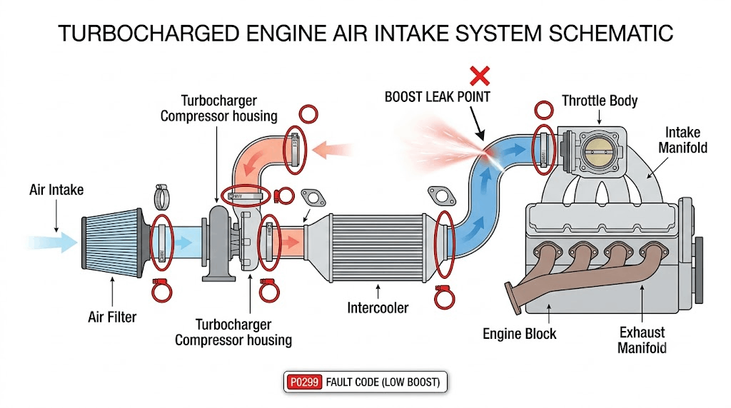
A boost leak occurs when pressurized air escapes from the intake system between the turbocharger compressor and the engine’s intake manifold. Unlike vacuum leaks (which draw unmetered air into the system), boost leaks let metered air out — reducing the mass of air reaching the cylinders and forcing the ECU to compensate by enriching the fuel mixture.
The consequences cascade:
- Power loss: Less air means less combustion energy. Drivers notice sluggish acceleration, especially under load.
- Diagnostic trouble codes: P0299 (turbocharger/supercharger underboost) is the most common flag, but lean/rich mixture codes may also appear.
- Torque limiting: Modern ECUs detect underboost and reduce throttle response to protect the engine, making the vehicle feel gutless.
- Increased fuel consumption: The ECU compensates for perceived lean conditions by adding fuel, wasting gas without producing power.
- Turbo overspeed: To maintain target boost, the wastegate stays closed longer, spinning the turbine faster than designed. Over time, this accelerates bearing wear and shortens turbo lifespan .
The root causes typically fall into three categories: material failure (hoses swelling or cracking under pressure/heat), connection failure (clamps loosening from vibration or thermal cycling), and installation error (oily surfaces, undersized clamps, or mismatched fittings).
Common Leak Points
Hose Connections
Hose-to-fitting junctions are the single most frequent source of boost leaks. Rubber hoses degrade over time — ozone cracking, heat embrittlement, and oil contamination all weaken the material. Even new hoses fail if they’re the wrong type for the application.
A critical distinction: “Silicone hoses resist expansion better” only applies to 3–4 layer polyester or aramid-reinforced silicone hoses. Thin-wall vacuum tubes without reinforcement are not suitable for pressurized boost applications . Confusing the two leads to catastrophic failures. We’ve seen shops install standard vacuum-grade silicone on turbo outlets, only to have the hose balloon and split within days. Reinforcement layers carry the tensile load; without them, internal pressure does the work.
Connection geometry matters too. A hose pushed only halfway onto a barb can hold under vacuum at idle — negative pressure pulls the joint tight — but it pops off the moment boost builds past a few PSI and pushes the joint apart. Always seat hoses fully — you should feel resistance as the inner lining passes over the barb’s ridge. If it slides on effortlessly, the fit is too loose.
Intercooler Pipes
Intercooler piping runs from the turbo outlet through the intercooler core and back to the throttle body. These sections experience both high pressure (up to 25+ PSI in modified builds) and significant temperature swings. Aluminum pipes expand and contract with heat, which can loosen clamp connections over time. Plastic end tanks on stock intercoolers are prone to cracking at the seam, especially on vehicles with 100,000+ miles.
Check for:
- Cracks at pipe welds or bends
- Loose clamps at intercooler inlet/outlet
- Oil residue around connections (oil seepage indicates a slow leak)
- Deformation from impact damage (common on lifted trucks or off-road vehicles)
Turbo Inlet/Outlet
The turbocharger itself has several potential leak points:
- Compressor outlet: The connection between the turbo housing and the charge pipe. Factory rubber couplers here are notorious for splitting after 80,000 miles.
- Wastegate actuator rod: A worn or loose rod allows the wastegate to flutter, creating inconsistent boost and audible chattering.
- Turbo flange gaskets: Metal-to-metal joints between the turbo and downpipe/exhaust manifold rely on proper gasket seating and even bolt torque. Uneven tightening creates gaps that leak exhaust gases (not boost, but still problematic).
Detection Methods
Symptoms Checklist
Before tearing anything apart, confirm the symptoms match a boost leak rather than another issue:
- Whistling or hissing sound under acceleration (the telltale sign of escaping pressurized air)
- Reduced power, especially above 3,000 RPM
- Check engine light on (underboost or related codes)
- Poor throttle response or hesitation
- Increased fuel consumption without driving habit changes
- Black smoke from exhaust (over-fueling due to lean correction)
If multiple symptoms align, proceed to physical inspection.
Testing Procedures
Visual inspection: Start with the engine off and cool. Look for:
- Cracked, swollen, or oily hoses
- Loose or missing clamps
- Disconnected vacuum lines
- Oil residue around fittings (indicates slow leakage)
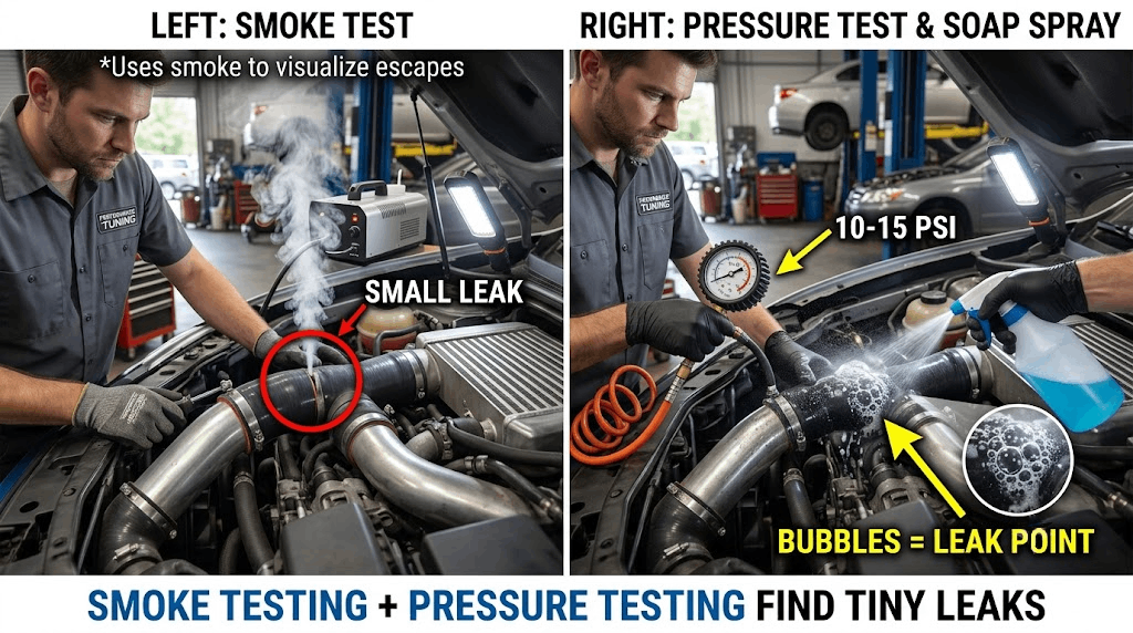
Smoke test: The gold standard for finding small leaks. A smoke machine introduces visible vapor into the intake system while the engine is off. Any escaping smoke pinpoints the leak location. This method catches leaks too small to hear or feel.
Pressure test: Disconnect the intake pipe after the turbo and cap it. Use a hand pump or compressed air (regulated to 10–15 PSI) to pressurize the system. Listen for hissing or apply soapy water to suspected areas — bubbles form at leak points. Never exceed the turbo’s rated pressure; overpressurizing can damage seals.
Boost gauge monitoring: Install a temporary boost gauge and monitor readings during a test drive. If the gauge shows lower-than-expected boost at wide-open throttle, or if boost drops suddenly mid-pull, a leak is likely present. Compare against manufacturer specifications for your vehicle.
Boost Leak Prevention Strategies
Clamp Selection: T-Bolt vs. Worm-Drive
Not all clamps are created equal. Worm-drive clamps (the standard hardware-store variety with a screw-and-band design) are fine for low-pressure vacuum lines, but they’re a leading cause of boost-side failures. Under sustained pressure and vibration, the band stretches, the screw backs out slightly, and the clamp loses tension. We see this repeatedly in comeback cases.
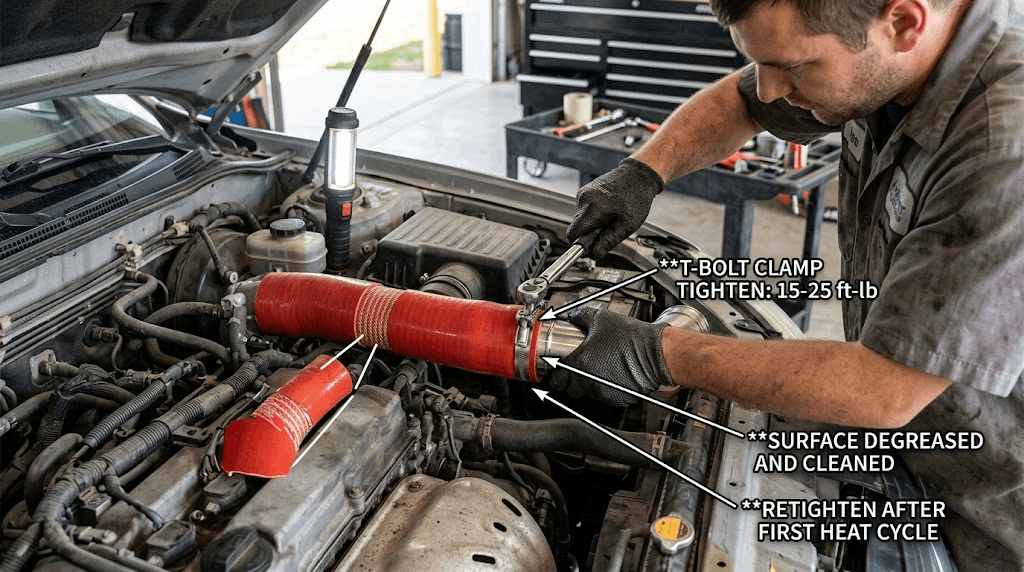
Use T-bolt clamps for all pressurized boost connections. T-bolt designs use a solid T-shaped bolt that pulls the band ends together with uniform force, resisting loosening from vibration. They distribute clamping pressure evenly around the circumference, preventing the localized stress points that cause hose deformation.
Installation tip: Ensure mating surfaces are clean and oil-free before tightening. Oil acts as a lubricant, allowing the hose to slip under pressure even with proper clamp torque . Wipe fittings with brake cleaner or isopropyl alcohol, then install the hose and clamp. Torque to specification (typically 15–25 ft-lbs for 2-inch connections), then re-check after the first heat cycle.
For our full line of reinforced silicone and SS304 turbo components, see our Silicone Vacuum Hose Kits product page.
Material Selection: Cold-Side vs. Hot-Side
Temperature dictates material choice. The intake system splits into two thermal zones:
- Cold side: From the intercooler outlet to the throttle body. Temperatures here rarely exceed 180°C (356°F), even under heavy load. Standard reinforced silicone handles this range comfortably.
- Hot side: From the turbo compressor outlet to the intercooler inlet. Temperatures can reach 260°C (500°F) or higher, depending on boost level and ambient conditions. Standard silicone degrades at these temperatures; use high-temp silicone (rated to 300°C+/572°F+) or metal piping .
Don’t mix materials across zones. Installing cold-side silicone on the hot side guarantees premature failure. Conversely, using expensive high-temp material on the cold side wastes money without adding benefit.
For guidance on sizing, see our guide on How to Choose Vacuum Hose Size.
Surface Preparation
Cleanliness is non-negotiable. Oil, grease, or old sealant on mating surfaces prevents proper sealing. Even a thin film of crankcase vapor residue (common on older turbos with worn PCV systems) reduces friction enough to allow hose slippage under boost.
Procedure:
1. Remove old hose and clamp
2. Clean fitting with brake cleaner or isopropyl alcohol
3. Inspect for burrs or damage — deburr if necessary
4. Apply a tiny amount of assembly lubricant (ATF or silicone spray) to ease installation — this is different from leaving surfaces oily; the lubricant evaporates or absorbs, leaving no slip plane
5. Install new hose, ensuring full seating on the barb
6. Position clamp and torque to spec
Maintenance Schedule
Boost systems aren’t “install and forget.” Thermal cycling, vibration, and pressure pulses all contribute to gradual degradation. A proactive maintenance schedule prevents roadside failures.
After initial installation:
- Re-torque all clamps after the first 50–100 miles of driving (first heat cycle)
- Visually inspect for leaks or loose connections
Ongoing maintenance:
- Every oil change (3,000–5,000 miles): Quick visual check of hoses and clamps
- Every 10,000 miles: Full inspection — remove clamps, check hose condition, verify seating
- After track days or heavy towing: Immediate inspection, as sustained high-RPM operation accelerates wear
- Annually: Smoke test or pressure test to catch slow leaks before they become problems
Replace immediately if you notice:
- Swelling or softening of hoses
- Cracks or brittleness
- Oil saturation (indicates internal liner failure)
- Clamp corrosion or stretching
For step-by-step installation procedures, refer to our Silicone Hose Installation Guide.
FAQ
Q: Can a small boost leak damage my turbo?
Yes, indirectly. When boost leaks, the ECU keeps the wastegate closed longer to reach target pressure, causing the turbo to spin faster than designed. Sustained overspeed accelerates bearing wear and can lead to premature turbo failure. Fix leaks promptly.
Q: Is it okay to use regular vacuum hose for boost applications?
No. Vacuum hoses are designed for negative pressure (suction), not positive pressure. Under boost, they swell, soften, and eventually split. Always use reinforced hoses rated for the expected pressure and temperature.
Q: How tight should T-bolt clamps be?
Typically 15–25 ft-lbs for 2-inch connections, but consult the clamp manufacturer’s specifications. Overtightening crushes the hose or distorts the pipe; undertightening allows slippage. Use a torque wrench for consistency.
Q: Can I reuse silicone hoses after removing them?
It depends. If the hose shows no swelling, cracking, or oil saturation, and the inner liner is intact, reuse is acceptable. However, silicone loses some elasticity after heat cycling. For critical boost applications, replacement is safer than reuse.
Q: What’s the best way to prevent boost leaks long-term?
Use the right materials (reinforced silicone, T-bolt clamps), ensure clean/oil-free surfaces during installation, re-torque after initial heat cycles, and follow a regular inspection schedule. Prevention is cheaper than diagnosis and repair.
Conclusion
Boost leak prevention comes down to three things: correct materials for the application, proper installation technique, and consistent maintenance. Don’t cut corners on clamps or hoses — the cost of a quality component is negligible compared to a tow bill or turbo replacement.
Need Custom Turbo Components?
LEDAUT manufactures reinforced silicone turbo hoses with SS304 fittings, T-bolt clamps, and custom components. We support OEM/ODM projects for distributors and performance shops worldwide. Contact LEDAUT for custom specifications tailored to your application requirements.